
Overview of SSD Structure and Basic Working Principle(2)
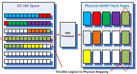
HOST accesses SSD through LBA (Logical Block Address). Each LBA represents a Sector (generally 512B in size) and the operating system generally accesses SSD in 4K. We call the basic unit of HOST accessing SSD as the HOST Page. Within SSD, FLASH Page is the basic unit to access FLASH between SSD master and FLASH and we call FLASH Page as Physical Page. Every time a HOST Page is written, the SSD controller will find a Physical Page to write the HOST data. So that map is recorded inside the SSD at the same time. With this mapping, the next time HOST needs to read a HOST Page, the SSD knows where to read the data from FLASH.
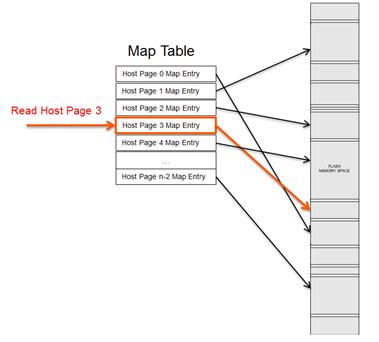
SSD contains a Map Table internally. Every time HOST Page is written, a new mapping relationship will be generated, which will be added (the first time written) or changed (overwrite) the Map Table. When reading a HostPage, SSD first looks up the Physical Page corresponding to the HostPage in the Map Table, and then accesses Flash to read the corresponding Host data.
How big is a Map Table? Suppose we have a 256GB SSD, Taking 4KB Host Page as an example, there are about 64M (256GB/4KB) Host pages in total, which means that SSD needs a Map Table of 64M size. Each Entry in the Map Table stores Physical Page Address. If it is 4Byte (32bits), then the size of the whole Map Table is 64M*4B = 256MB. For most SSDS, we can see that they have onboard DRAM, which is mainly used to store this mapping table. SSD based on sandforce master is exception, which do not support on-board DRAM. So where does its mapping exist? When SSDs work, most of their mappings are stored in FLASH, and some are stored on on-chip RAM.
When HOST needs to read some data, for SSD with DRAM, it just look up the mapping table in the DRAM to get the physical address and then access FLASH to get HOST data. During this time, Flash is only accessed once. While for SSD with Sandforce, it first check whether mapping table Host page corresponding to is in RAM. If it is there, Flash is read by mapping table directly. If not, it first read the mapping table from FLASH, and then read the Host data based on that mapping. This means that SSDs with Sandforce need to read FLASH twice to get HOST data out compared with DRAM, resulting in the underlying effective bandwidth halved. So we can see the random read performance of Sandforce-based SSDs is not ideal.
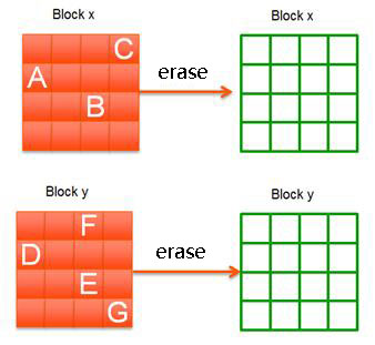
Go back to the previous SSD write operation. If users want to write new data when the entire SSD is filled, some data must be deleted to get room to write again. Some data in blocks become invalid or old in the process of users deleting and writing data. As shown in the figure below (the green square represents valid data, while the red square represents invalid data):
The data in the Block is old or invalid, meaning that there is no mapping pointing to it and it is replaced by a new mapping. So users will not have access to these FLASH Spaces. For example, there is a Host page A stored in block X, mapping relationship is A-> X. Later, HOST rewrote the HOST Page. Since FLASH cannot overwrite, SSD must find an unwritten location to write new data, assuming Y. At this point, the previous mapping relationship is dissolved and a new mapping relationship is established: A-> Y. The data at location X gets old called junk data.
As the HOST continues to write, the FLASH storage space shrinks until it runs out. If this garbage data is not cleared in time, HOST cannot be written.
SSD has an internal garbage collection mechanism, of which basic principle is to gather valid data from several blocks (non-junk data, shown in the green square above) to a new Block, then erase the blocks to create new usable blocks.
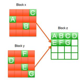
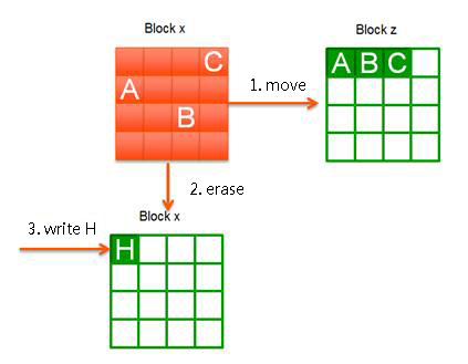
In the figure above, the valid data on Block X is A, B, C and Block Y is D, E, F and G. The red Block is invalid data. The garbage collection mechanism is to find an unwritten Block Z, then move the valid data of Block X and Block Y to Block Z. So Block X and Block Y don’t have valid data and can be erased to become two usable blocks.
With a new SSD, you'll find that writing is fast because an available Block is easy to find to write at first. However, as you use SSDS, you will find that it slow down. The reason is that you often need to do the above garbage collection if writing new data after SSDS are full-moving valid data from several blocks to a Block, erasing the original Block and writing your Host data. This takes a lot more time than just finding a usable Block to write, so it slows down.
Assuming that HOST is writing 4KB of data (H), the SSD starts garbage collection because there are too few currently available blocks. As you can see from the figure above, Block X reads and writes Page A, B, and C to Block Z. Then Block X is erased to write the HOST data. From the Host point of view, it only writes 4KB of data. But it actually writes 4 pages (Page A, B, C writes Block Z, and 4KB of data H writes Block X) in the inside of SSD.
Principle of garbage collection

Look at this picture again. Recycle Block X, there are 3 valid pages on it, read and write 3 pages to complete the recycling of the whole Block; when you recycle Block Y, you need to read and write four valid pages. Obviously, it's faster to recycle Block X than it is to recycle Block Y. That illustrates a simple truth: the less data available on a Block (the more garbage), the faster it can be recycled.
Related Articles:
Overview of SSD Structure and Basic Working Principle(1)
How will SSD develop in data center in the future? - Memory Storage
Comprehensive understanding of SSD and NAND Flash (1)